

HyperJam Wall-Mount Installation Guide

HyperJam 60" & 72" Wall Mount Hoop Installation Guide
Everything you need to safely install your HyperJam Adjustable Wall Mount Basketball Hoop. The installation process is identical for both the 60" and 72" models.
Installation Tutorial
Safety Information
⚠ READ BEFORE INSTALLINGFailure to follow these instructions may result in serious injury, death, or property damage.
- Consulting a licensed contractor or structural engineer is highly recommended.
- Minimum three people required for installation.
- Do not hang or climb on the rim or backboard.
- Inspect the system before each use.
Before You Begin
Important NoticeWe strongly recommend consulting a licensed contractor or structural professional before installation. The manufacturer assumes no responsibility for damage or injury resulting from improper installation.
Installation Requires
- 3 capable adults
- Ability to lift components up to 106 lbs (48 kg)
- Estimated time: 2-3 hours
- Wall fasteners are not included and must be selected based on wall type
Tools Required (Not Included)
- Hammer drill
- Appropriate drill bits
- 4 ft level
- Tape measure
- Socket set and wrench set
- Torque wrench
- Ladder
- Safety glasses
Structural Requirements
⚠ CRITICAL: WALL BACKING REQUIREMENTSThe bracket must be anchored to structural backing capable of supporting minimum 1,000 pounds of downforce. *Wall fasteners are not included and must be selected based on wall type*
✓ Suitable
- Solid concrete (min. 8" thick)
- Solid brick (structural)
- Wood framing 2x6+ studs (with proper backing
- Steel I-beam or column
✗ Not Suitable
- Drywall or plaster alone
- Brick veneer
- Paneling or siding
- Hollow-core walls
- Metal stud framing
Sheetrock / Drywall Walls
Backing required at 88" to 134" from floor. Retrofit: doubled 2"x10" or 2"x12" lumber fastened into 3 studs. Min. 4" thick and 1,000 lb downforce rating required.
Concrete Walls
8"+ solid concrete at the correct height does not require additional backing. Verify 1,000 lb capacity with a structural engineer.
⚠ DO NOT PROCEED WITHOUT PROPER BACKINGFailure may result in property damage, serious injury, or death.
Assembly Parts List
| No. | Description | Qty |
|---|---|---|
| A | Wall Frame | 1 |
| B | Upper Extension Arm | 1 |
| C | Lower Extension Arm | 1 |
| D | Spring-Assist Cartridge | 1 |
| E | Height Actuator | 1 |
| F | Backboard (60" x 36" or 72" x 42") | 1 |
| G | Rim | 1 |
| H | Height Sticker | 1 |
Technical Specifications

| Model | Backboard | Height Range | Overhang at 10ft | Overhang at 7.6ft | Frame Bottom |
|---|---|---|---|---|---|
| W-72 | 72" x 42" | 7.5-10 ft | 39" | 43" | 94-1/4" |
| W-60 | 60" x 36" | 7.5-10 ft | 39" | 43" | 94-1/4" |
Installation Steps
1
Mount Wall Frame
- Measure 83.5" from the playing surface and mark a horizontal reference line.
- Position Wall Frame (A) aligned to the mark. Level it perfectly plumb and level.
- Mark anchor hole locations, drill holes, insert wall anchors, then secure frame with 12 sets of washers and bolts.

2
Install Extension Arms
- Attach Upper Arms (B) to Wall Frame (A) — do not fully tighten yet.
- Attach Lower Arm (C) to Wall Frame (A). Tighten all while keeping pivot points free.


3
Install Height Actuator & Spring Assist
⚠ Do NOT remove the spreader tube on the Spring Assist until the hoop is fully installed.
- Attach Spring Assist (D) and Height Actuator (E) to Wall Frame (A) and Lower Arm (C) as shown.

4
Install Triangle Brackets on Backboard
- Attach 4 triangle brackets to backboard using twelve M8x40 bolts, four flat washers, and 12 locknuts.

5
Attach Backboard
⚠ Minimum three people required for this step.
- Crank Extension Arm (C) as low as possible.
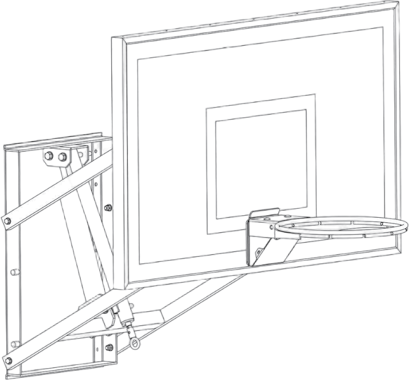
- Attach Backboard (F) to Lower Arm (C) then Upper Arms (B).

6
Rim Assembly
- Mount Rim (G) with rubber gasket to backboard bracket using hardware #13, #2, #3, #4.
- Attach spring box cover with #14 and #15. Fix net by twisting loops 90° clockwise.
7
Apply Height Sticker
- Crank rim to exactly 10 ft and mark on Height Actuator (E).
- Apply Height Sticker (H) aligning pencil mark with the 10 ft mark.

Final Inspection
Do not use if any components appear loose or damaged.
- All nuts, bolts, and fasteners fully tightened.
- Wall frame securely anchored and does not move when force is applied.
- All pivot points move freely without binding.
- System raises and lowers smoothly through full height range.
- Rim and backboard are level and properly aligned.
Routine Maintenance
Hardware
- Periodically inspect and tighten all nuts, bolts, and mounting hardware.
Structural
- Inspect frame, arms, and brackets for wear or damage. Replace any compromised components immediately.
Rust & Paint
- Inspect for rust or chipped paint. Clean and touch up as needed. Discontinue use if rust has penetrated structural components.
Replacement PartsUse only manufacturer-approved parts. Contact support for replacements.
Need Help With Installation?
Questions about installation, replacement parts, or want to speak with a specialist?